Expert FRP Manufacturer

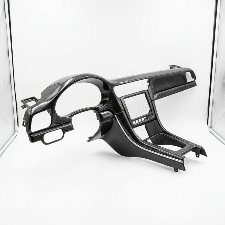
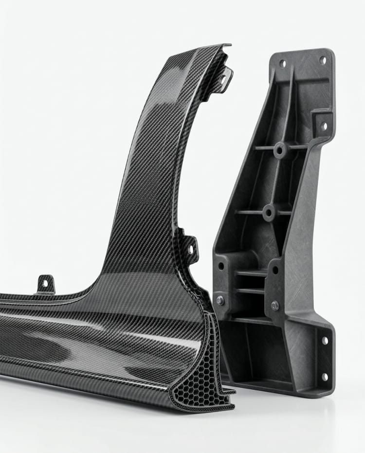
Carbon Fiber Automotive Trim

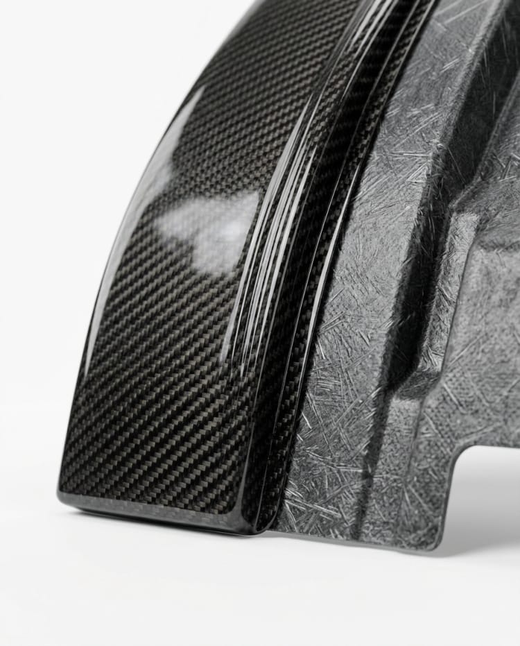
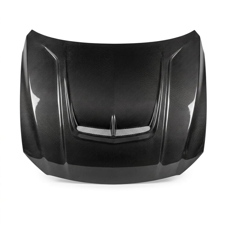
Match the carbon fiber automotive trim to the mating part. Confirm vehicle reference part and clip locations; agree gap targets, weave orientation and gloss sample before tooling.

Carbon Fiber Automotive Trim

Project Type

Carbon Fiber Automotive Trim

Core Material

Carbon Fiber

Lead Time

Confirmed After Design Review

Surface Finish

Clear-Coat Finish

How we make it

Project Development Process

Review the mating part and use conditions for the carbon fiber automotive trim; define gap targets and weave orientation before fabrication and gloss sample before final inspection.

Part Geometry Review
01

Part Geometry Review

Review the mating part and use conditions. Compare vehicle reference part and clip locations with the supplied drawing, sample or site survey before approving the part definition.

  • Record vehicle reference part
  • Confirm clip locations
Carbon Layup and Forming
02

Carbon Layup and Forming

Plan layup, trim and attachment references. Set the proposed build and interface details around gap targets and weave orientation; agree any unverified requirement before fabrication.

  • Coordinate gap targets
  • Agree weave orientation
Clear Finish and Protection
03

Clear Finish and Protection

Check edge fit, visible finish and protection. Verify gloss sample against the agreed inspection plan and protect the part for its delivery route.

  • Review requirement for gloss sample
  • Confirm packing and delivery handling

Scope at a glance

Applications + Custom Options

Applications

Built for visible composite components

For visible interior or exterior vehicle trim, confirm vehicle reference part and clip locations against the buyer drawings. The mating vehicle part and attachment method determine fit and visible gaps.

  • Application: visible interior or exterior vehicle trim.
  • Fit inputs: vehicle reference part and clip locations, checked against the project reference.
  • Interface inputs: gap targets and weave orientation, agreed with the buyer or installer.
  • Site and delivery inputs: gloss sample, confirmed before the part split is approved.

Custom options

What buyers can specify

Specify vehicle reference part, clip locations, gap targets, weave orientation and gloss sample in the supplied drawings or project specification. These inputs guide part geometry, mounting and visible finish.

  • Drawing package: vehicle reference part and clip locations.
  • Interface details: gap targets and weave orientation, with acceptance criteria.
  • Project conditions: gloss sample, confirmed with the engineer or installer.
  • Commercial brief: finish reference, quantity and delivery limits.

Browse nearby applications using the same category and manufacturing approach.

Need to know

Common buyer questions

Which drawings are needed for the carbon fiber automotive trim?

Send a drawing or sample showing vehicle reference part and clip locations, together with the mating equipment or site reference. GFIND can review feasibility against these inputs.

How should gap targets and weave orientation be defined before tooling?

Show gap targets and weave orientation on the approved drawing. The buyer and GFIND should agree the related fit tolerances and inspection method before tooling.

What conditions affect the carbon fiber automotive trim quotation?

State gloss sample, expected quantity and delivery constraints. List any inspection records or tests the buyer requires in the RFQ.